As I continue to build my robot, one of the important elements is having a controller that I can use to manually move and test the motors.
There are a few examples of projects others have done that make controllers that are Arduino or pi based for example James Bruton’s smart robot remote below
Building a Touchscreen Smart Robot Remote – YouTube
For myself, I want to use an RC remote that I already have, so I am keen to hook up the RC receiver to the Arduino and read in the signal parameters so I can use them to control motors and so forth right from the Arduino.
I will be using the Radiolink AT10II 2.4G 12 Channels RC Transmitter and Receiver in this project but any RC controller and receiver should work just fine.

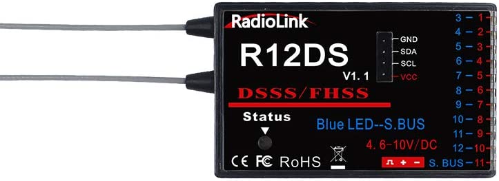
This RC combo is very featured and works very well. For the price I paid I am extremely happy with the quality and features.
For the Arduino board, I am going to use an Arduino MEGA 2560. This is a workhorse for me, I have used the board in many projects, 3d printers and so on. It is well featured, fast and has plenty of memory for whatever I want to throw at it. It also has a number of interrupt pins we can use – These are pins. that detect when something changes, and lets us react to that in code. So when I move the stick on the RC controller, the Arduino detects it, and reads the new value.
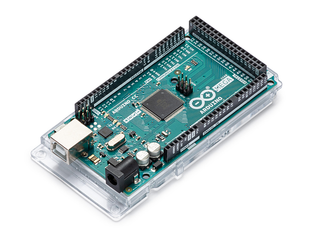
Wiring
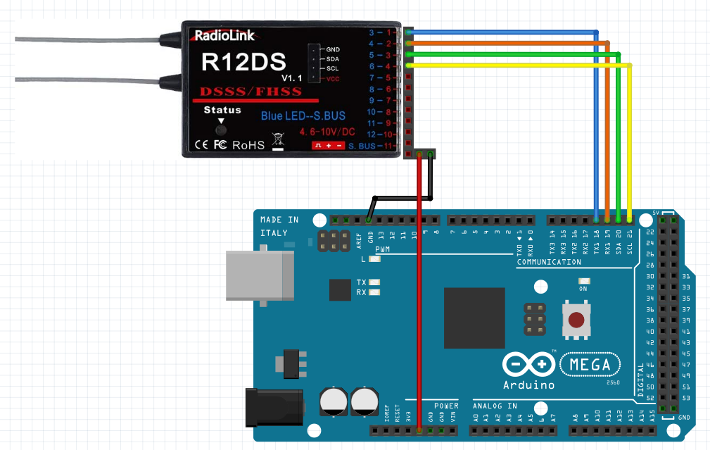
The Arduino Mega 2560 has 6 interrupt pins available (2, 3, 18, 19, 20, 21). we are going to connect four of these to our receiver to read the signal. Other Arduino boards have different interrupt pins, you can see the pins on this Arduino article for other boards. attachInterrupt() – Arduino Reference
We only need 6 wires for our demo. We connect any of the ‘-‘ pins to the Arduino ground. we connect any of the ‘+’ pins to the Arduino 5V since the receiver takes 4.6v to 10v. Then we connect pin 1 to 18, 2 to 19, 3 to 20 and 4 to 21. If we wanted more channels then we could use pins 2 and 3 on the Arduino also, but for our demo this is enough.
Code
The first thing we are going to do is set out the pins for our input from the RC Receiver. I also added a variable for our baud rate, and some variables to hold the data needed to decode each RC channel. You’ll note I annotated my channels with what they correspond to on the controller I’m using. Your controller may not use the same channels.
// Set the size of the arrays (increase for more channels)
#define RC_NUM_CHANNELS 4
// Set up our receiver channels - these are the channels from the receiver
#define RC_CH1 0 // Right Stick LR
#define RC_CH2 1 // Right Stick UD
#define RC_CH3 2 // Left Stick UD
#define RC_CH4 3 // Left Stick LR
// Set up our channel pins - these are the pins that we connect to the receiver
#define RC_CH1_INPUT 18 // receiver pin 1
#define RC_CH2_INPUT 19 // receiver pin 2
#define RC_CH3_INPUT 20 // receiver pin 3
#define RC_CH4_INPUT 21 // receiver pin 4
// Set up some arrays to store our pulse starts and widths
uint16_t RC_VALUES[RC_NUM_CHANNELS];
uint32_t RC_START[RC_NUM_CHANNELS];
volatile uint16_t RC_SHARED[RC_NUM_CHANNELS];Code language: Arduino (arduino)The pins correspond to the wiring we performed earlier. The next step is to attach the interrupts. for this we need to create some basic functions to call when our pin changes value. In the code below we first set up our serial connection to the computer so we can send and retrieve values. Then we set our input pins to all be Input only. Finally we enable the interrupt on each of the pins. We also say that the interrupt needs to call a function for each pin so the code knows what to do when the interrupt is hit
// Setup our program
void setup() {

  // Set the speed to communicate with the host PC
  Serial.begin(SERIAL_PORT_SPEED);

  // Set our pin modes to input for the pins connected to the receiver
  pinMode(RC_CH1_INPUT, INPUT);
  pinMode(RC_CH2_INPUT, INPUT);
  pinMode(RC_CH3_INPUT, INPUT);
  pinMode(RC_CH4_INPUT, INPUT);

  // Attach interrupts to our pins
  attachInterrupt(digitalPinToInterrupt(RC_CH1_INPUT), READ_RC1, CHANGE);
  attachInterrupt(digitalPinToInterrupt(RC_CH2_INPUT), READ_RC2, CHANGE);
  attachInterrupt(digitalPinToInterrupt(RC_CH3_INPUT), READ_RC3, CHANGE);
  attachInterrupt(digitalPinToInterrupt(RC_CH4_INPUT), READ_RC4, CHANGE);

}
Code language: Arduino (arduino)
So the four pins will call four functions (READ_RC1, READ_RC2, READ_RC3, READ_RC4). So our next step us to write these four functions. Since each function is just going to measure the input, we can actually send all four of these functions to one place – in this case another function Read_Input().
// Thee functions are called by the interrupts. We send them all to the same place to measure the pulse width
void READ_RC1() {
   Read_Input(RC_CH1, RC_CH1_INPUT);
}
void READ_RC2() {
   Read_Input(RC_CH2, RC_CH2_INPUT);
}
void READ_RC3() {
   Read_Input(RC_CH3, RC_CH3_INPUT);
}
void READ_RC4() {
   Read_Input(RC_CH4, RC_CH4_INPUT);
}
Code language: Arduino (arduino)
Read_Input() is probably the most complicated part of our whole process. To understand what it is doing, you have to understand a little about PWM, and this could be a whole post of its own. What you should know is that RC controllers communicate by sending pulses of varying width down the wire. the width of the pulse defines the value. when a pin goes high (gets voltage) the pulse starts, when it goes low (voltage turns off) the pulse ends.
Every time a pin changes, it is going to trigger the interrupt, and so we can store the start of the pulse and then when the interrupt is triggered for the pulse ending we can report how many milliseconds have elapsed and this defines the value on that channel.
// This function reads the pulse starts and uses the time between rise and fall to set the value for pulse width
void Read_Input(uint8_t channel, uint8_t input_pin) {
  if (digitalRead(input_pin) == HIGH) {
    RC_START[channel] = micros();
  } else {
    uint16_t rc_compare = (uint16_t)(micros() - RC_START[channel]);
    RC_SHARED[channel] = rc_compare;
  }
}
Code language: Arduino (arduino)
So far, the interrupts will fire independent of our main program loop, but as we loop we want to use these values, so one final step is to copy the values from the arrays used for the interupts and turn them into something easy to use. Every time the program loops, we will run the rc_read_values() function to pull the values and then I’m converting the values into floats for ease of use.
void loop() {

  // read the values from our RC Receiver
  rc_read_values();


}
Code language: Arduino (arduino)
Here’s the read values function that does the array copy for us. While it runs it disables the interrupts so it can complete uninterrupted (HA!).
// this function pulls the current values from our pulse arrays for us to use.
void rc_read_values() {
  noInterrupts();
  memcpy(RC_VALUES, (const void *)RC_SHARED, sizeof(RC_SHARED));
  interrupts();
}
Code language: Arduino (arduino)
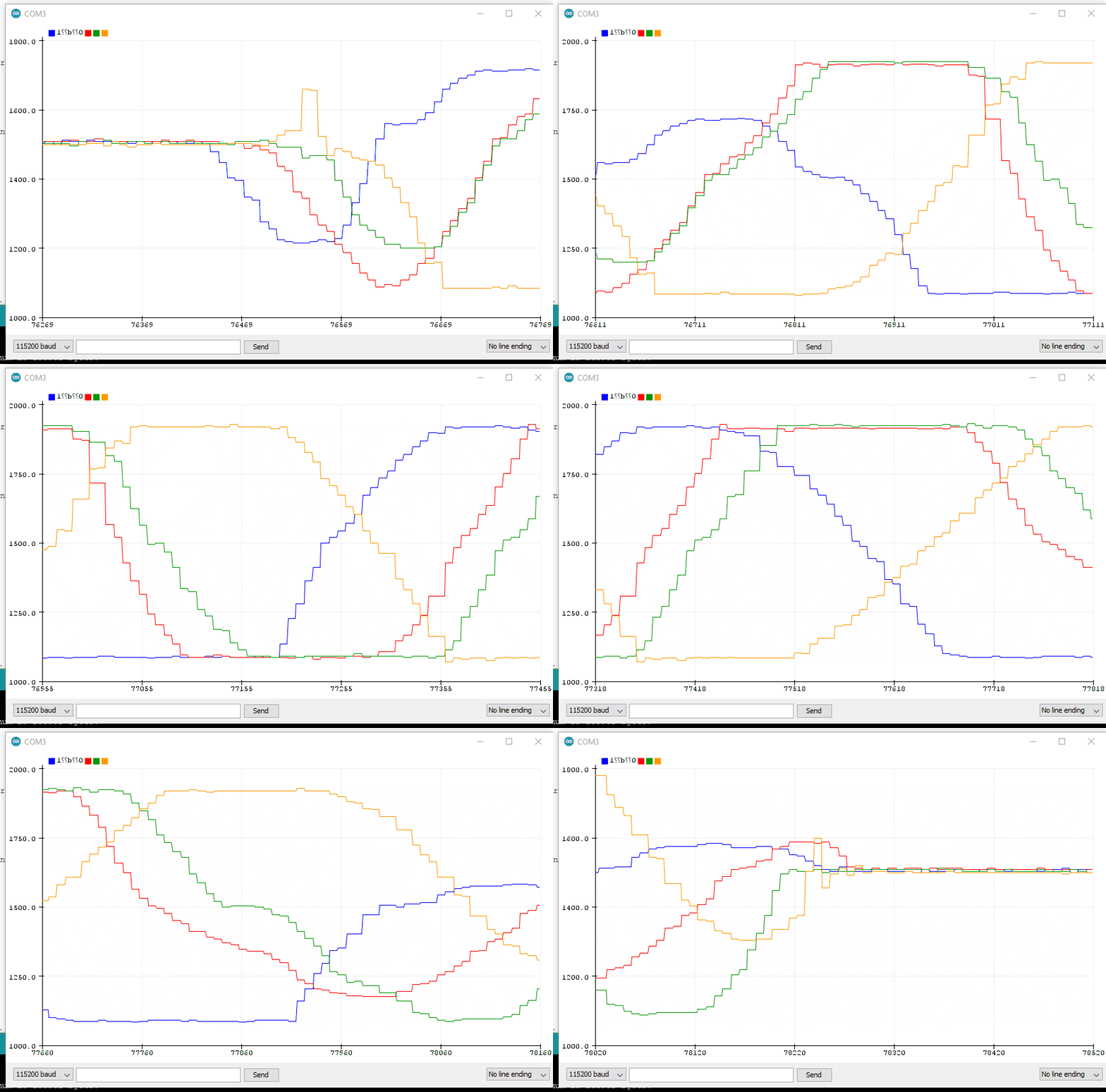
So every loop our four variables will be filled with their values from our RC controller. RC values are supposed to range from 800 to 2200 with the mid point being around 1600, so you can expect the values of the four variables to fall within this range. With my controller I’m seeing values range from around 1085 to 1920 with a mid point of 1500 so your mileage may vary here and its important to tune to your setup.
Visualizing Inputs
We will cover the usage and refinement of these values in the next post, but I wanted share with you a trick for visualizing the values.
First, we add the following to the end of our loop. You can write this section any way you choose, all we are doing is writing our four values separated by commas out to the serial port
  // output our values to the serial port in a format the plotter can use
  Serial.print(  RC_VALUES[RC_CH1]);  Serial.print(",");
  Serial.print(  RC_VALUES[RC_CH2]);  Serial.print(",");
  Serial.print(  RC_VALUES[RC_CH3]);  Serial.print(",");
  Serial.println(RC_VALUES[RC_CH4]); Code language: Arduino (arduino)
Next we are going to use the Serial Plotter.
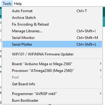
What this will do is take any values that it is given over the serial channel and plot them on a chart. As you move the sticks on the RC, you should see the values change on the chart as you do. The serial plotter is a fantastic way to visualize what is happening in your code.
Here’s what the visualizer looks like in action:
Full Code
You can download the full code for this blog article from my github below.
Next time
Now we are able to read our RC inputs, we need to make them useful. In the next article I am going to show you how to implement dead zones so the sticks don’t feel so twitchy. I am also going to implement fail safe so that we can tell if the controller got disconnected or ran out of battery and we can react to that. I will also show you how to control a motor with the values we are getting from the RC controller.
