The Taig 5019CR I ordered did not come with limit switches or even mounts to install them. coming from the 3d printer and gantry cnc world, I am used to having limit switches to establish a homing position and then to move out from there so I can make things repeatable.
When I made these limit switches I had some contstraints in mind:
- I did not want to have to drill and tap the machine. I wanted something that would bolt on
- I have 48V motors and so I didn’t want proximity switches as they are 24V and I did not have anything to hand to convert the voltage
- I wanted to 3d print these as a prototype
I designed 3 mounts in fusion 360 very quickly. I will circle back when free time stretches out before me like a barren desert and I have nothing better to do and design them to be made on the taig itself:)
First you will need the following components:
- some switches, I recommend these. They are very well made and my mounts are designed to fit these specifically
2. Some wire – this wire is incredible, and shielded. I have found nothing better
The Mounts
X Limit Switch
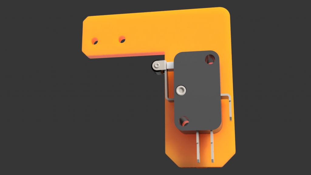
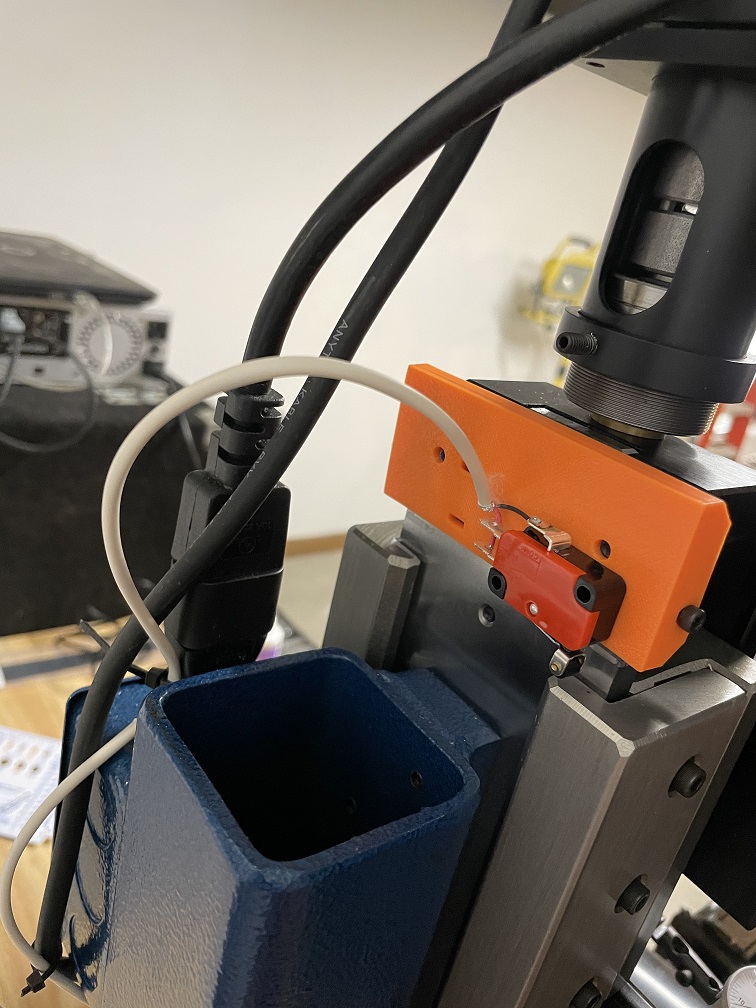
This fits on the right of the table, you slide two square nuts into the groove on the front, and screw it in, on the rear side is a locator to snug up against the side of the table to make sure its the right distance and that is doesn’t flex
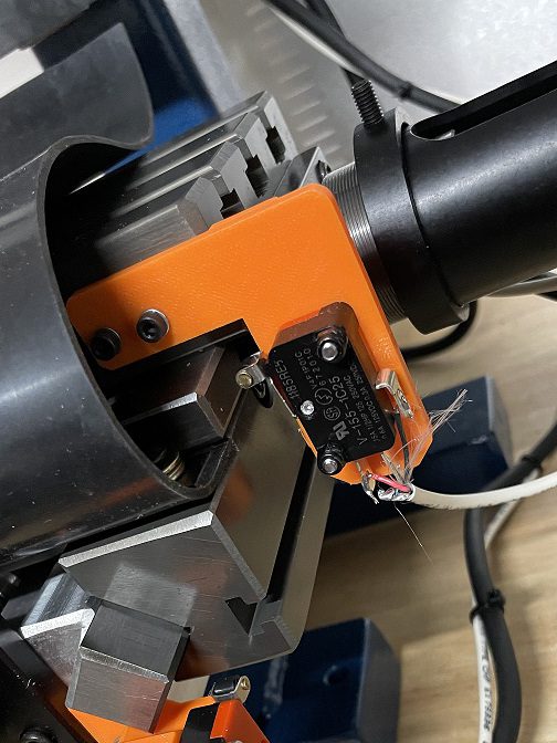
Y Limit Switch

On my machine I actually had a tapped hole right on the right hand box way so I screwed right to that.
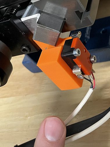
Z Limit Switch
This just clamps on to the back of the Z axis. you cant put it on wrong as its set to side right over the back. two M3 screws and M3 captive nuts provide the clamping force from left and right. there’s a little channel for zip ties to keep the wire out the way for you and provide cable relief.
The files
Grab the zip containing the files below
or get it from Thingiverse – I uploaded it there too:
