Refining Controller Input
Without a shadow of a doubt the feedback I get most from those of you kind enough to watch my videos is “where’s the second part of the arduino RC controller video?”
Well I made you all a promise, and so better late than never, here’s Part 2 on using an RC controller with an Arduino
Last time we covered the bits you’ll need, the hook ups, the code for the basic controller, how to read values and how to plot them to the screen.
If you are coming here without watching the last video I’d really suggest
taking a look because everything we are going to cover today builds on what we did last time : Click here to See it on YouTube
In the Part 2 Video we’ve added the following concepts
- Channel Inversion
- DeadZone Adjustment
- Value Translation
- Failsafe Processing
If you’ve seen the video, then you’ve come here for the code. I’ve posted snippets below, but you can grab it from my github here
General Flow
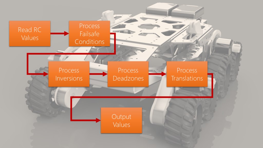
The flow of how we process signals from the RC is as below. We read out values, then we go through various processing steps to condition our signal for use.

By the end, we have values that are available to use however we see fit. the aim is to have outputs that match your use case for example thumb sticks that control a 0-90 degree servo, or a throttle that goes from 0-100%.
So let’s talk about the steps:
Failsafe
When the receiver goes out of range of the controller, or the batteries die on the controller, we have a serious problem, if the throttle was maxed and we cant react, then the car or robot will stay throttled up forever unless it see’s the controller again – bye bye plane 🙁
When this happens, the lag for the signal being received tends to go much higher (or never comes). we can detect this, and set the signal the program uses to whatever value we want. In code we specify this at the top:
// what should we set the value to if we cant see the RC controller?
uint16_t RC_FAILSAFE_VALUE[RC_NUM_CHANNELS] = { 1508, 1508, 1508, 1508, 1092 };Code language: JavaScript (javascript)
Inversions
What do you do when you press your stick up, but your value goes down? well we can deal with that in code, there’s a handy variable at the top to allow you to invert on a per-channel basis:
// Do we need to invert the input? 1 = yes, 0 = no
// Use this if your joystick goes the wrong way
uint16_t RC_INVERT[RC_NUM_CHANNELS] = { 1, 0, 1, 0, 1 };Code language: JavaScript (javascript)
Deadzones
Ever had it when a controller joystick never seems to sit at zero? maybe the springs are tired and it needs a bit of a buffer before it starts giving you values? well now we can specify the percentage deadzone in our file to take care of these issues:
// What percentage deadzone is allowed? values in percent e.g. 10 = 10%
uint16_t RC_DZPERCENT[RC_NUM_CHANNELS] = { 30, 30, 30, 30, 5 };Code language: JavaScript (javascript)
Translations
My RC controller generates pulse widths from about 1092 to 1924, Which is great, said no servo ever. What I’ve added is a bit of math I lovingly stole from stack overflow to translate those values into something you can use. I mapped it to -100 to 100 in my lesson, but you can do 0 to 360 for example instead and send it straight to your servo.
Values are specified at the top like this:
// some boundaries for our mapped values
float RC_TRANSLATED_LOW[RC_NUM_CHANNELS] = { -100, -100, -100, -100, 0 };
float RC_TRANSLATED_MID[RC_NUM_CHANNELS] = { 0, 0, 0, 0, 0 };
float RC_TRANSLATED_HIGH[RC_NUM_CHANNELS] = { 100, 100, 100, 100, 100 };
Code language: JavaScript (javascript)
Now It’s Over to you!
I’ve included a little code to show you what you would need to add a few servos that work off the translated values of the channels. Add the header, setup and loop elements to their respective parts in the main sketch.
  // Now its over to you!
  /*
     Now you can use the newly translated values in your project, you can access them like this:
     Channel 1 = RC_TRANSLATED_VALUES[0]
     Channel 2 = RC_TRANSLATED_VALUES[1]
     Channel 3 = RC_TRANSLATED_VALUES[2]
     etc

     assuming you set them to a range you can use, you could position a servo
     or drive a motor or even pass them through to an odrive or ROS
                here's an example:
                #include <Servo.h>
                Servo servo1; int servoPin1 = 9;
                Servo servo2; int servoPin1 = 10;
                Servo servo3; int servoPin1 = 11;
                void setup(){
                  servo1.attach(servoPin1);
                  servo2.attach(servoPin2);
                  servo3.attach(servoPin3);
                }
                void loop(){
                  servo1.write(RC_TRANSLATED_VALUES[0]);
                  delay(1000);
                  servo2.write(RC_TRANSLATED_VALUES[1]);
                  delay(1000);
                  servo3.write(RC_TRANSLATED_VALUES[2]);
                  delay(1000);
                }
  */Code language: JSON / JSON with Comments (json)
Thanks for reading
Hopefully lesson 2 has been enjoyable for you, can grab the full code from my github here. If you have any question please do get in touch. Perhaps next time I’ll connect this code to a servo and a motor, maybe even an ODrive 🙂
